
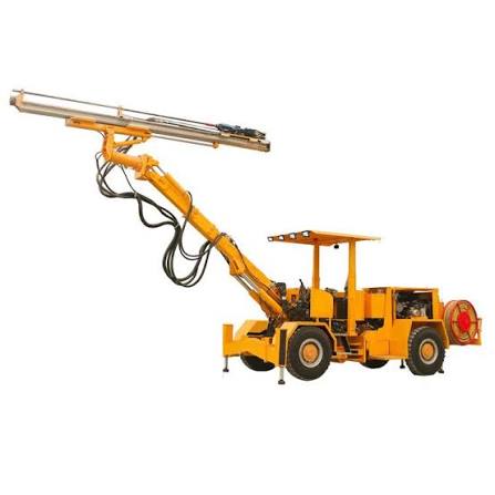
HONSFUID / DRILL
Rock drill rotation and feed
Use rotation pressure feedback to change feed speed under load and restore fast feed when released.
HONSFUID / SCHEMATICS
Project schematics
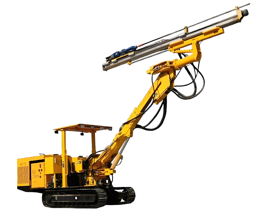
281 drilling rig hydraulic system · electric control

281 drilling rig hydraulic system · hydraulic pilot control
281 drilling rig hydraulic system · pilot control · 2025-04-01
Single-boom rock drill hydraulic schematic
Single-boom rock drill · electro-proportional valves · 2025-07-23
Dingli CYTJ45 · hydraulic schematic 1
01Rotation motor 250 cm³/rev reference
02No-load rotation 70 bar reference
0313 mm line × 24 m round trip
Public functional circuit
Functional diagram showing power and control paths. It is not an ISO 1219 installation schematic. Use approved project drawings for ports, valve positions, safeguards and settings.
ENGINEERING
Control logic
High rotation pressure requests slow feed; release restores fast feed. Retract delay and two-stage pressure control need sensor and valve response validation.
Design inputs
Design input / verify per project
COMPONENTS
Products and selection
- Drill valve assemblyCustom flow and pressure logic
- Cartridge manifoldIntegrated logic and test ports
- Directional and holding valvesSpecify per feed actuator
Products are candidate configurations. Confirm ratings, interfaces and compatibility with approved catalogs.
View catalogSUPPLIED PROJECT REFERENCE
Tunnel rock drill · electro-proportional hydraulic system
The supplied reference combines a machine photo, circuit drawing and component images. Open or download the original for review and product discovery.
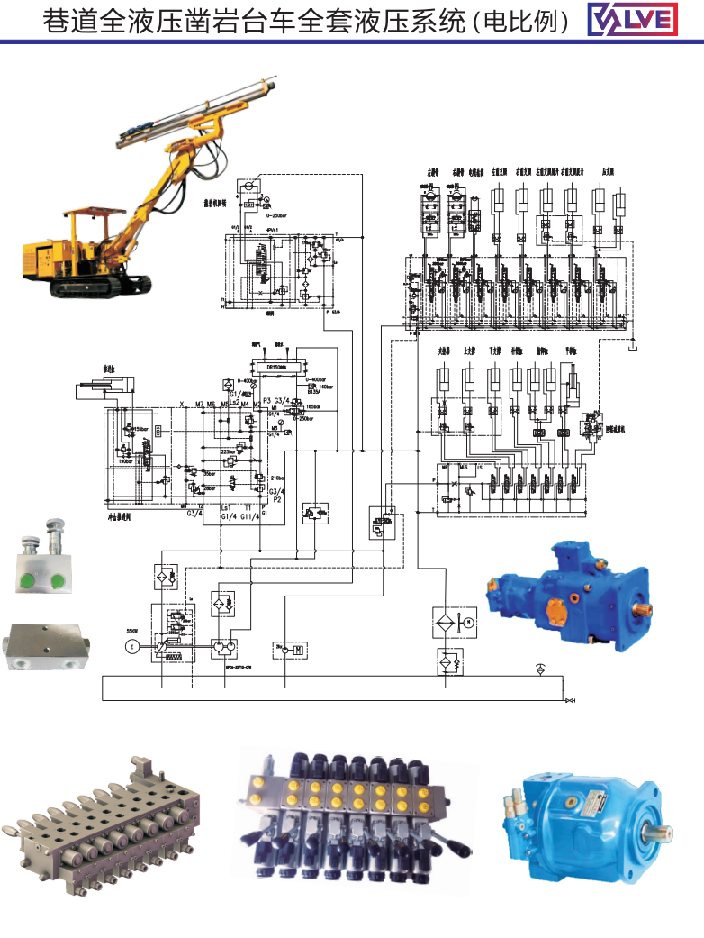
Original system reference
Small port labels and pressure settings are not sufficiently legible for installation or selection. Approved circuit, BOM, datasheets and CAD files are needed for detailed release.
Open full-size image Download original PNGComponent groups visible in the image
Electro-proportional sectional valve
Main motion-control group; verify sections, ratings and ports against approved drawings.
Hydraulic pump and motors
Power and rotary components are shown; exact model and displacement cannot be confirmed from this image.
Auxiliary manifolds and valves
Pressure, holding or logic functions require circuit and BOM confirmation.
Pilot control assembly
Control components are visible; verify signal type and connections.